DIY Splitkeyboard
Building a Custom Split Keyboard: From Concept to PCB
Overview
This project started since I wanted to try a splitkeyboard for a long time, but since they were pretty expensive in the past. I thought to myself why not use this as an opportunity to learn something new and create something I wanted to try for a long time. In addition I wanted to try an ortholinear for a change.
As a "proper" engineer I started with some research by looking what is available out there. I looked at some different design, like the ErgoTravel and what open source firmware I could use. Wirtting a complete new firmware would be way out of scope for this project. I settle on the QMK firmware together with an inexpensive STM32 MCU.
Why and What
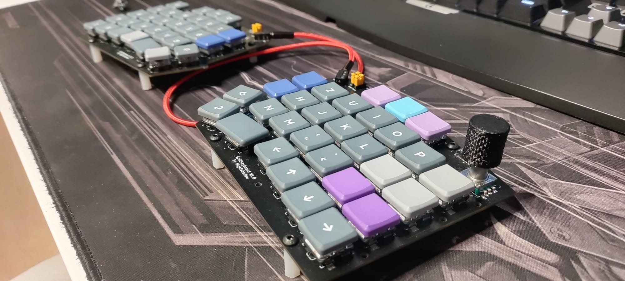
The primary motivation was to move away from standard layouts and explore the world split keyboard. I wanted a board that utilized the Kailh Choc Tactile switches for a slim profile and tactile feedback and standard MX swtiches for compatibility reasons. You can not go wrong with MX switches.
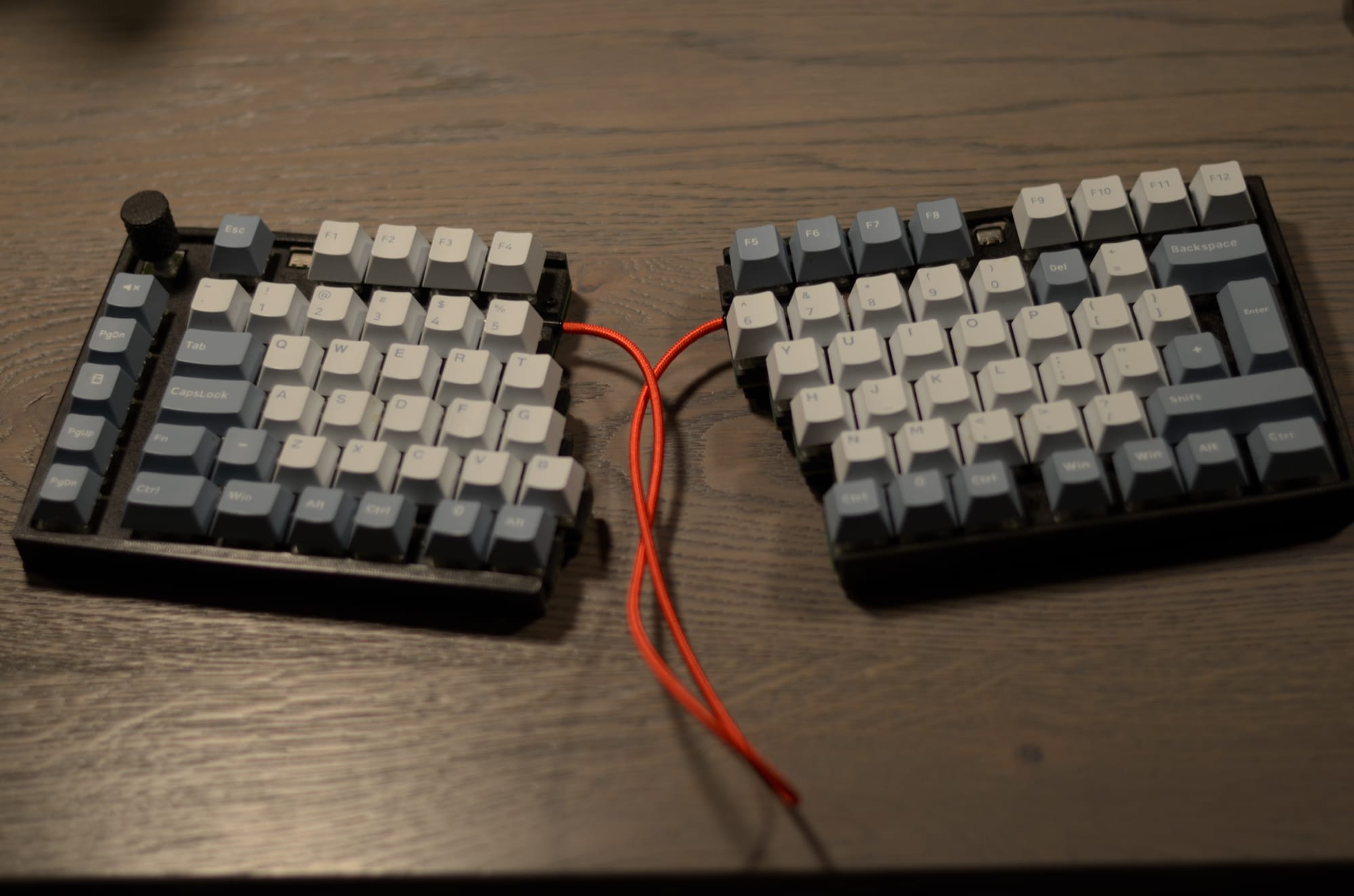
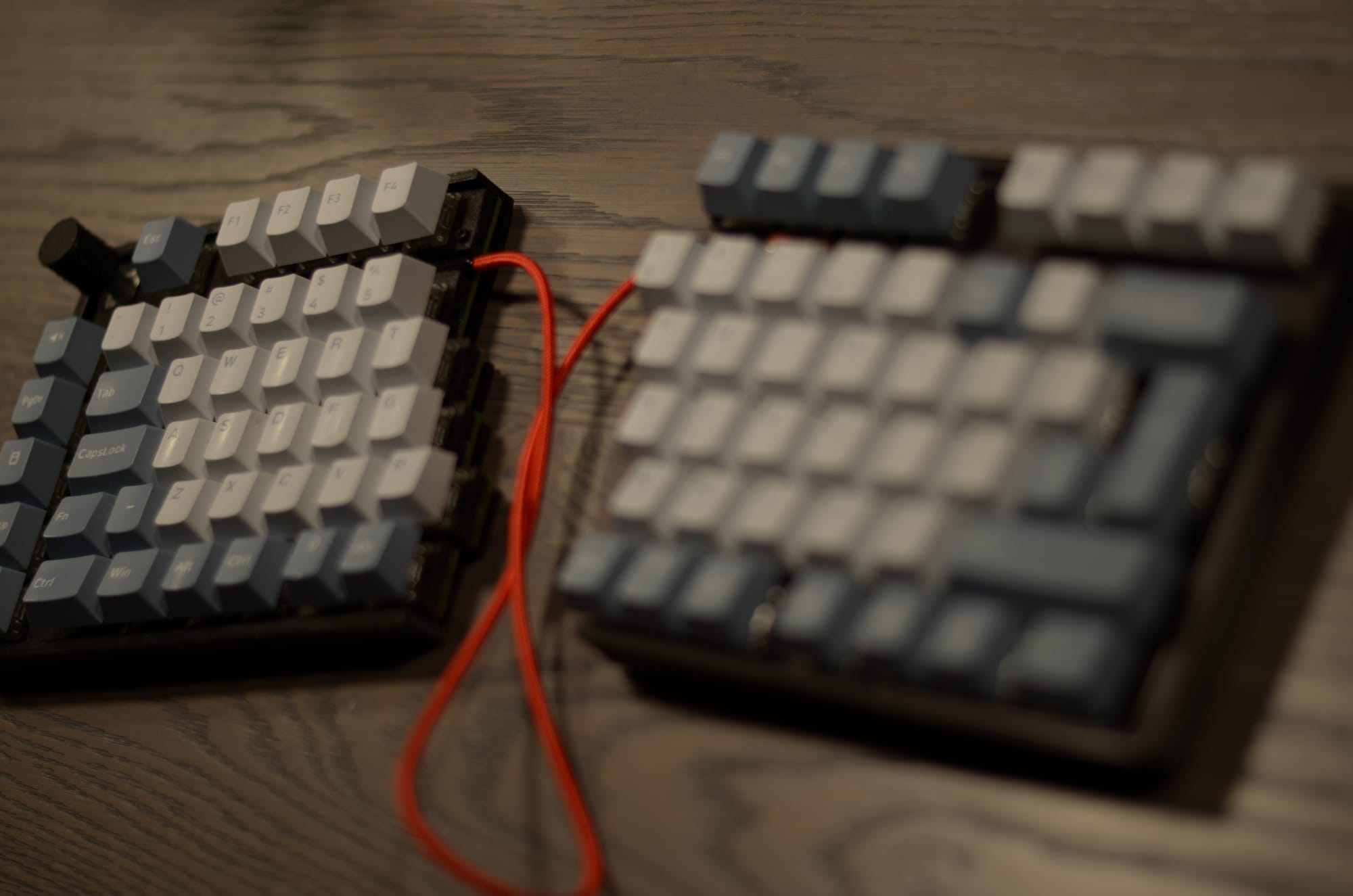
By splitting the keyboard, I can position the halves at shoulder width to improve posture and play around with different keybaord angles (x and y direction of course)
The final key technical requirements included:
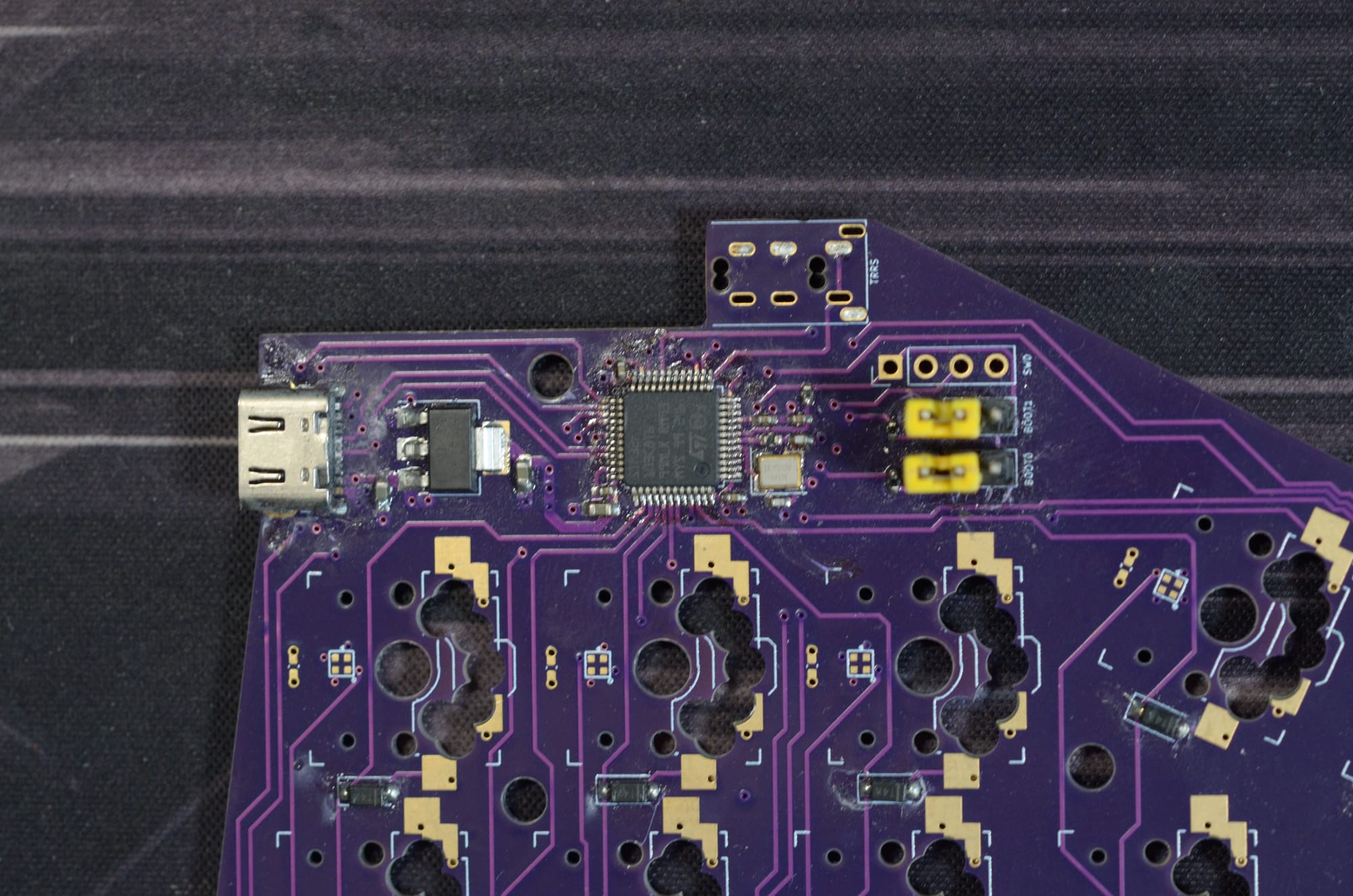
- MCU: STM32F103C8 (Bluepill style but integrated on PCB)
- Switches: Kailh Choc (Low Profile)
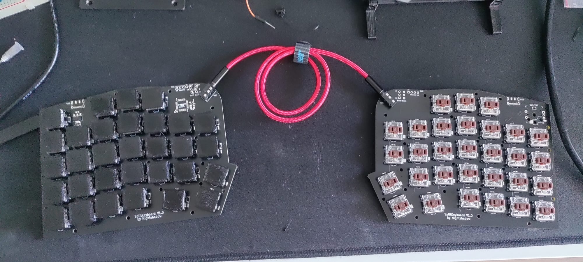
- Connectivity: USB C for data and TRRS for the link between halves
- Firmware: QMK with Serial Driver support
- Features: RGB per key lighting (SK6812-EC1515)
- Rotary Encoder for volume control
Planning and Designing
The design process involved bridging the gap between existing open source projects and my own requirements. Using the ErgoTravel and other keyboard that I can not remember anymore (I am sorry!) as a foundation. I wanted to have more keys accessible by my thumbs. Since I am using a german keyboard layout I wanted to have easy access to the different brackets [] and {} for programming.
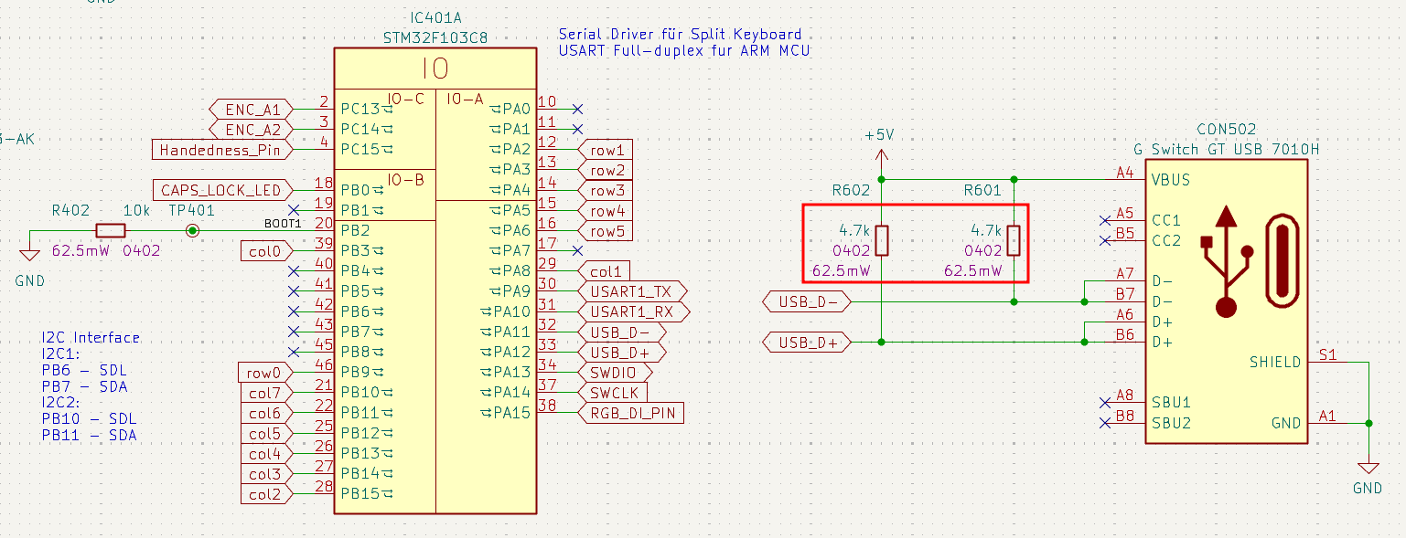
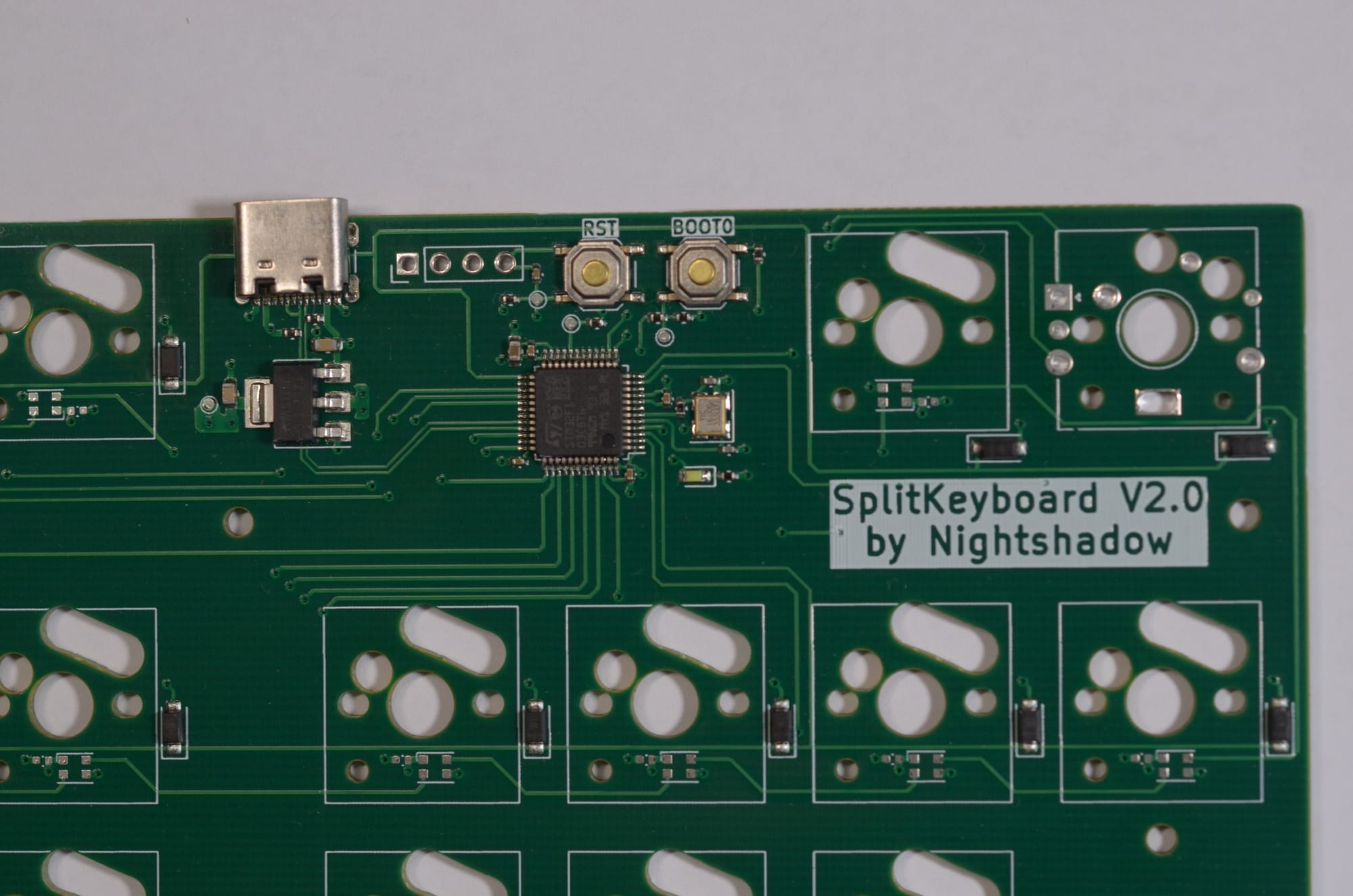
One of the biggest challenges during the planning phase was the USB implementation for the STM32F103C8. Unlike some ATmega chips, the STM32 requires specific pin configurations and pull up resistors to be recognized correctly by a PC.
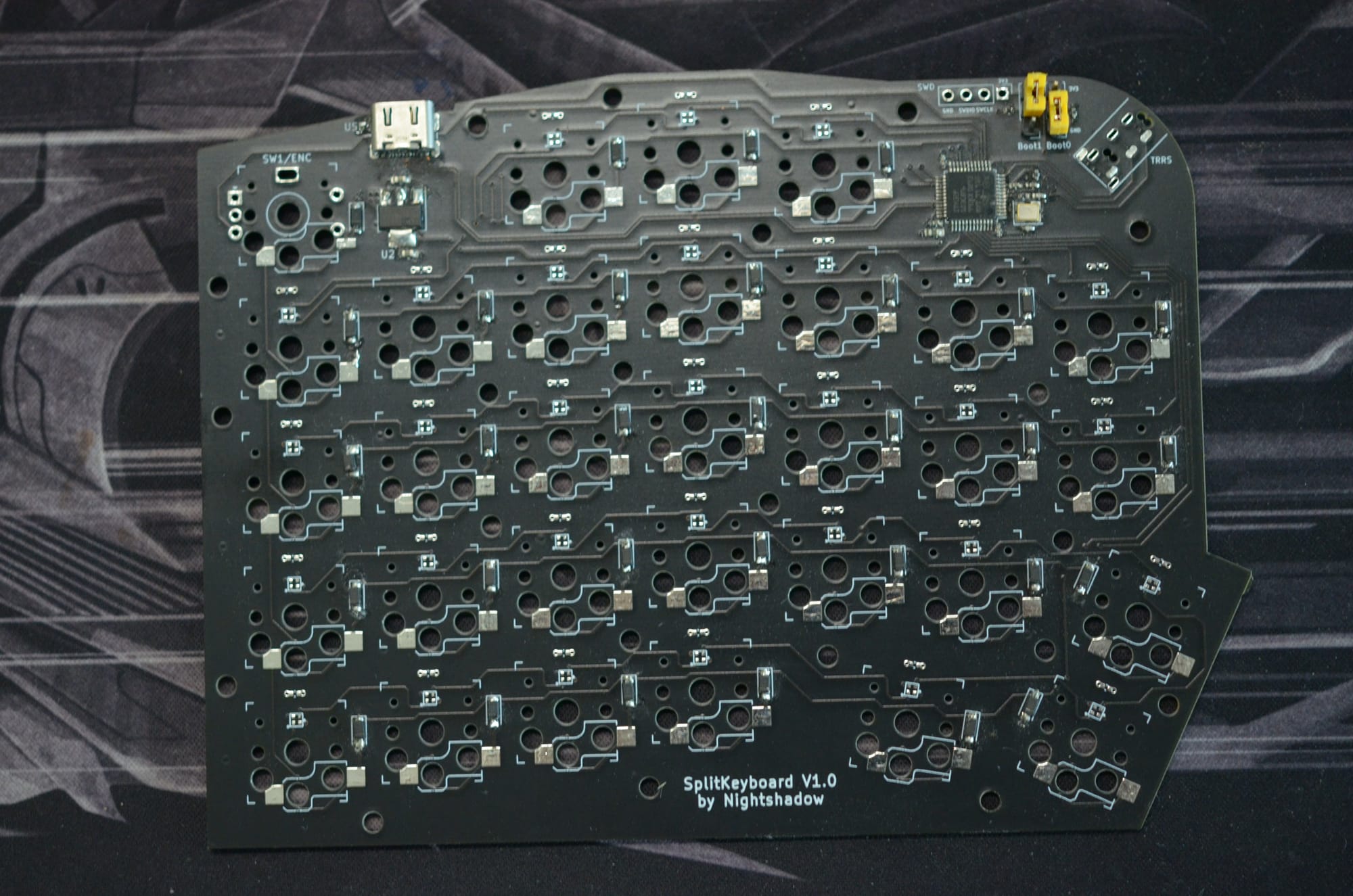
Version 1
The first iteration was about proof of concept. It focused on the core components: the MCU, the 27 keys per side, and the basic split functionality. The key layout and position was also a first test. It also feature a mirrored PCB design, which enables one PCB to be either the left or the right keyboard side. The keys are hot-swappable allowing for easy replacement and testing of different key switches.
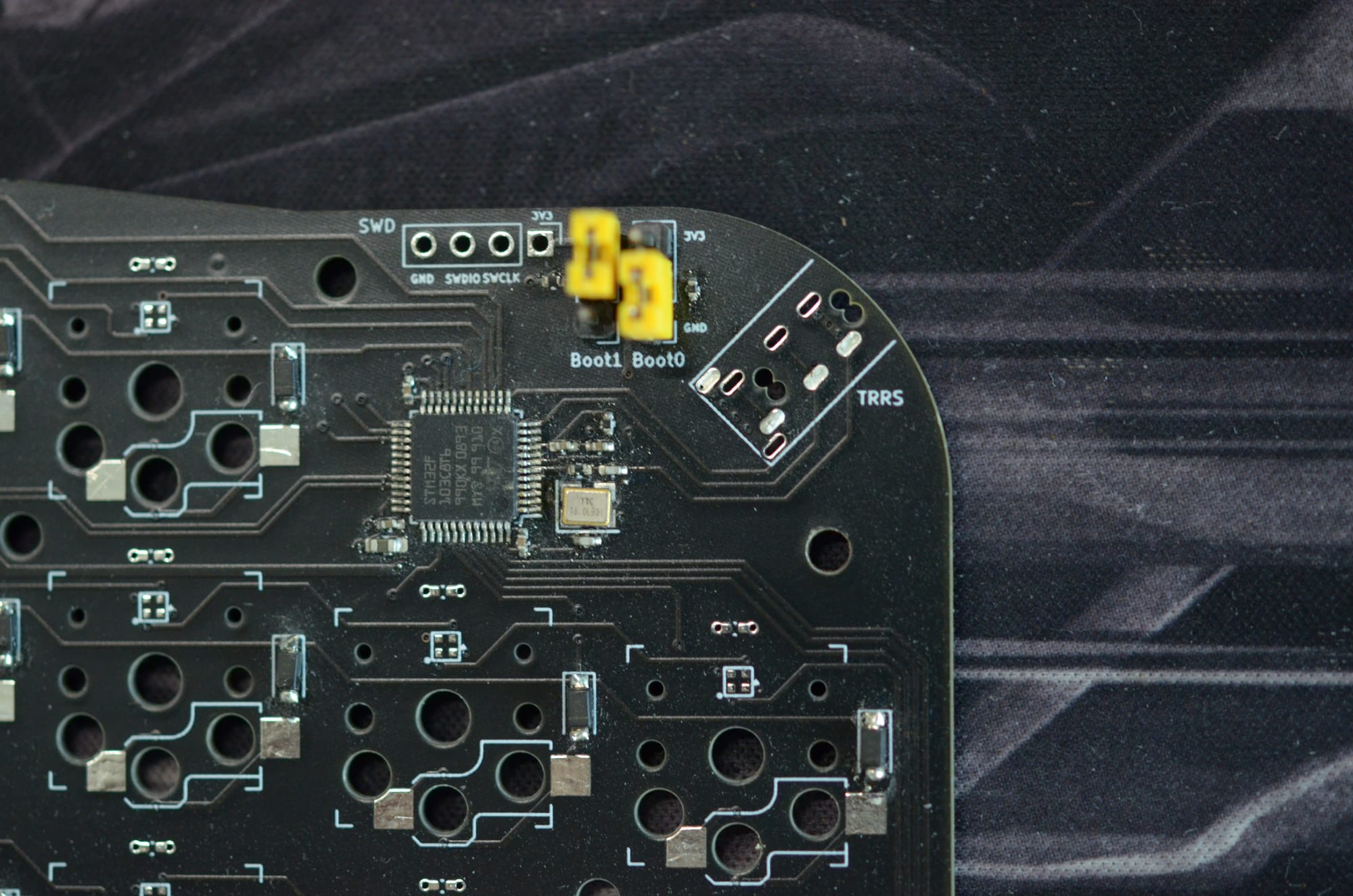
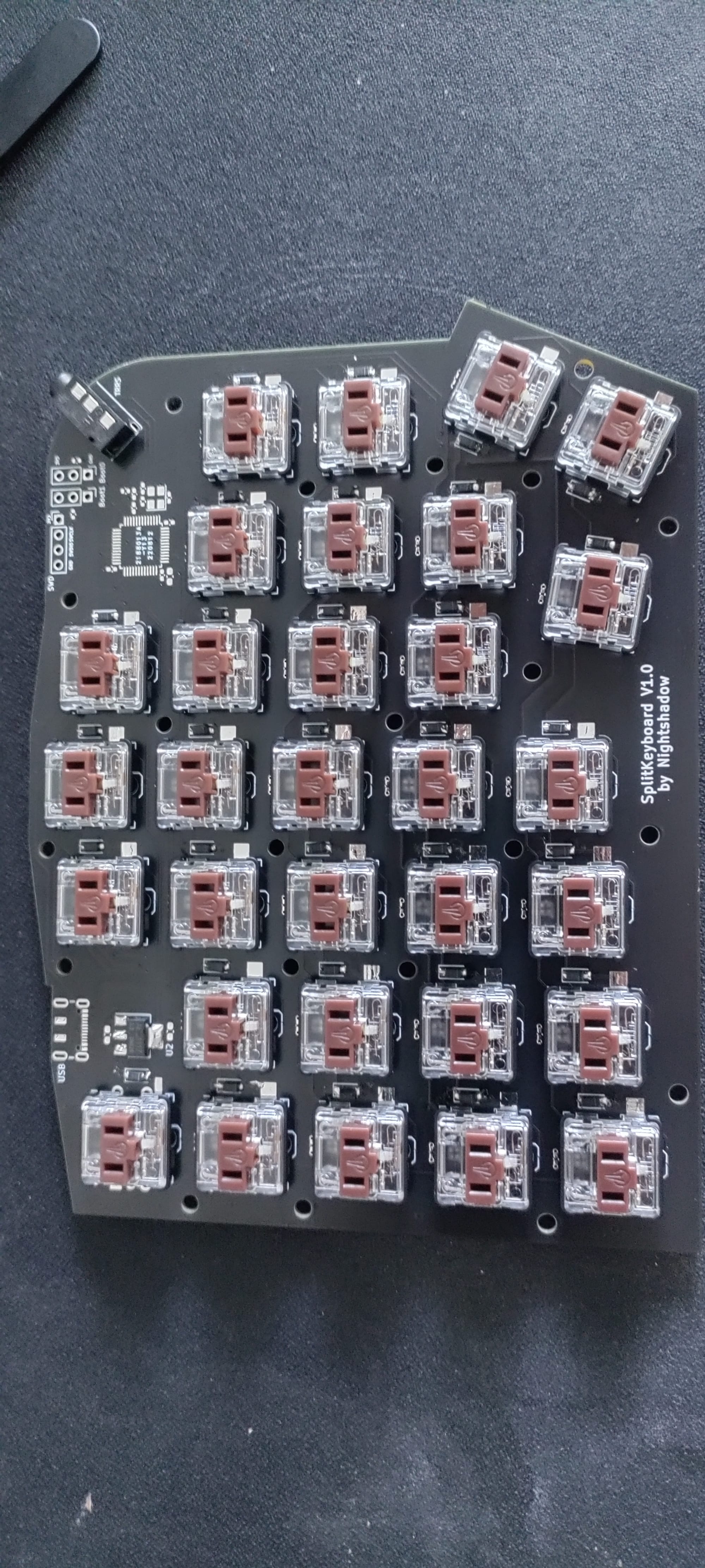
- Focus: Getting the STM32 to communicate over USB.
- Learning: Navigating the bootloader states. Setting Boot0 and Boot1 correctly is vital for flashing. I eventually settled on the STM32duino bootloader to allow for easier flashing via USB.
- I also figured out that the default STM32duino bootloader did not work with my hardware design, since I used a 16MHz high speed crystal. Therefore I had to compile the bootloader from scratch. I had to use the
#define XTAL16Mdefinition for theTARGET_GENERIC_F103_PC13. After flashing the resulting.binfile to the boards I was able to flash the qmk software. Side note: I had to create a VM with Ubuntu 16.04 to compile the bootloader successful, might be useful to know in the future. I believe the gcc version was causing issues on newer Ubuntu version that I used at the time.) - Firmware: Uploading and getting familiar with the QMK firmware and who the layouts are managed.
- QMK supports automatic detection of the left/right keybaord half by setting
SPLIT_HAND_PINpreprocessor to the dedicated input pin of the MCU. This allows to define two state in hardware by either pulling the pin LOW or HIGH. Each state represents left or right keyboard. Alternatively it is possible compile a binary for each of the halves by using these defines in the config.h file of the keybaord:#define MASTER_RIGHTor#define MASTER_LEFT
Issues
The biggest issue I had for the Version 1.0 were the missing 4.7k pull-ups on the USB Data lines. Without them the USB communication did not work.
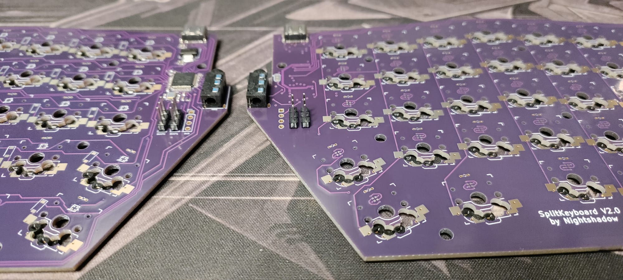
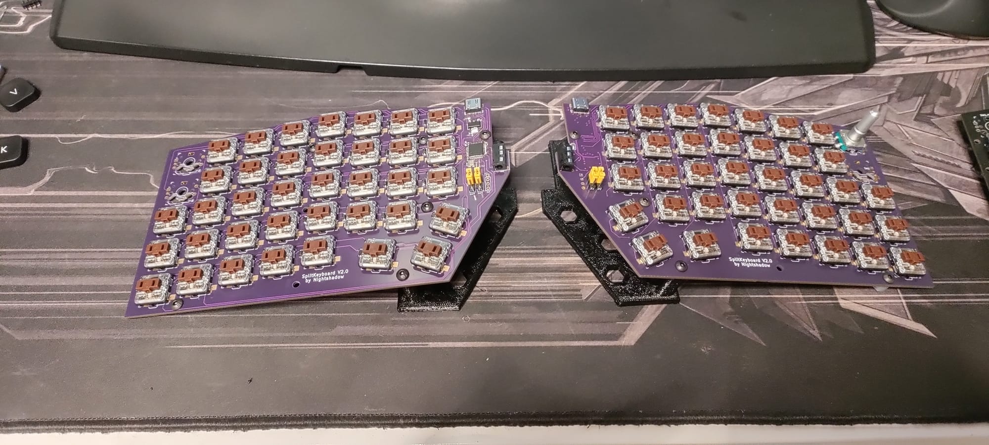
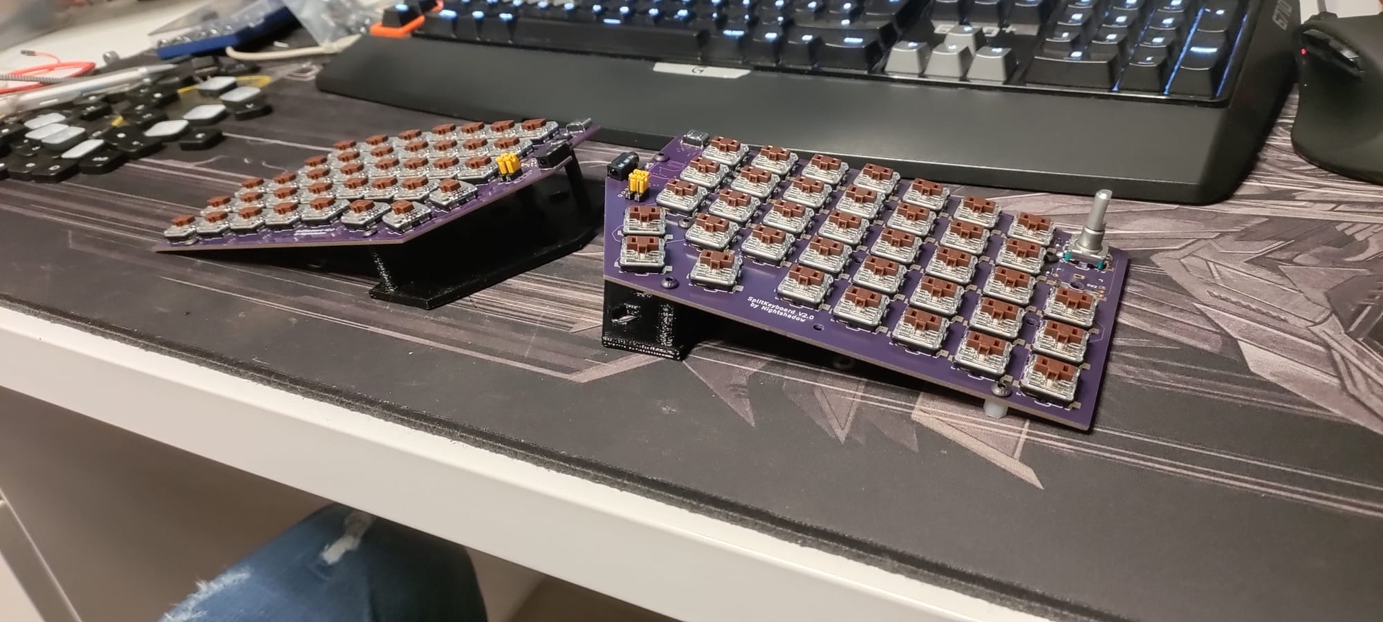
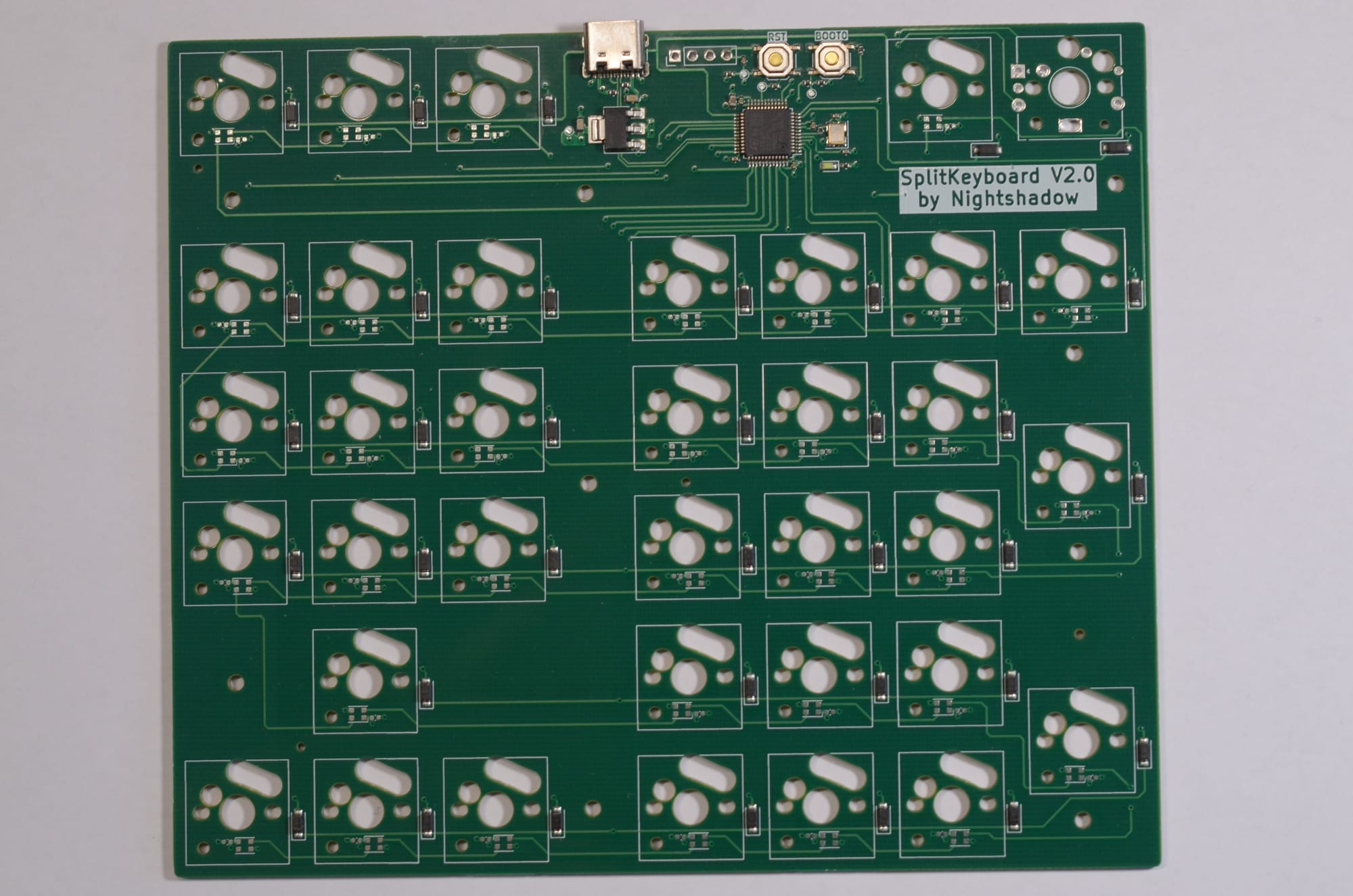
Version 2
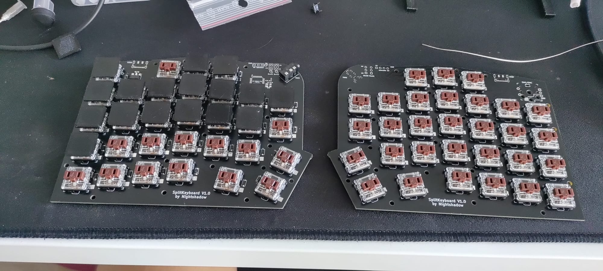
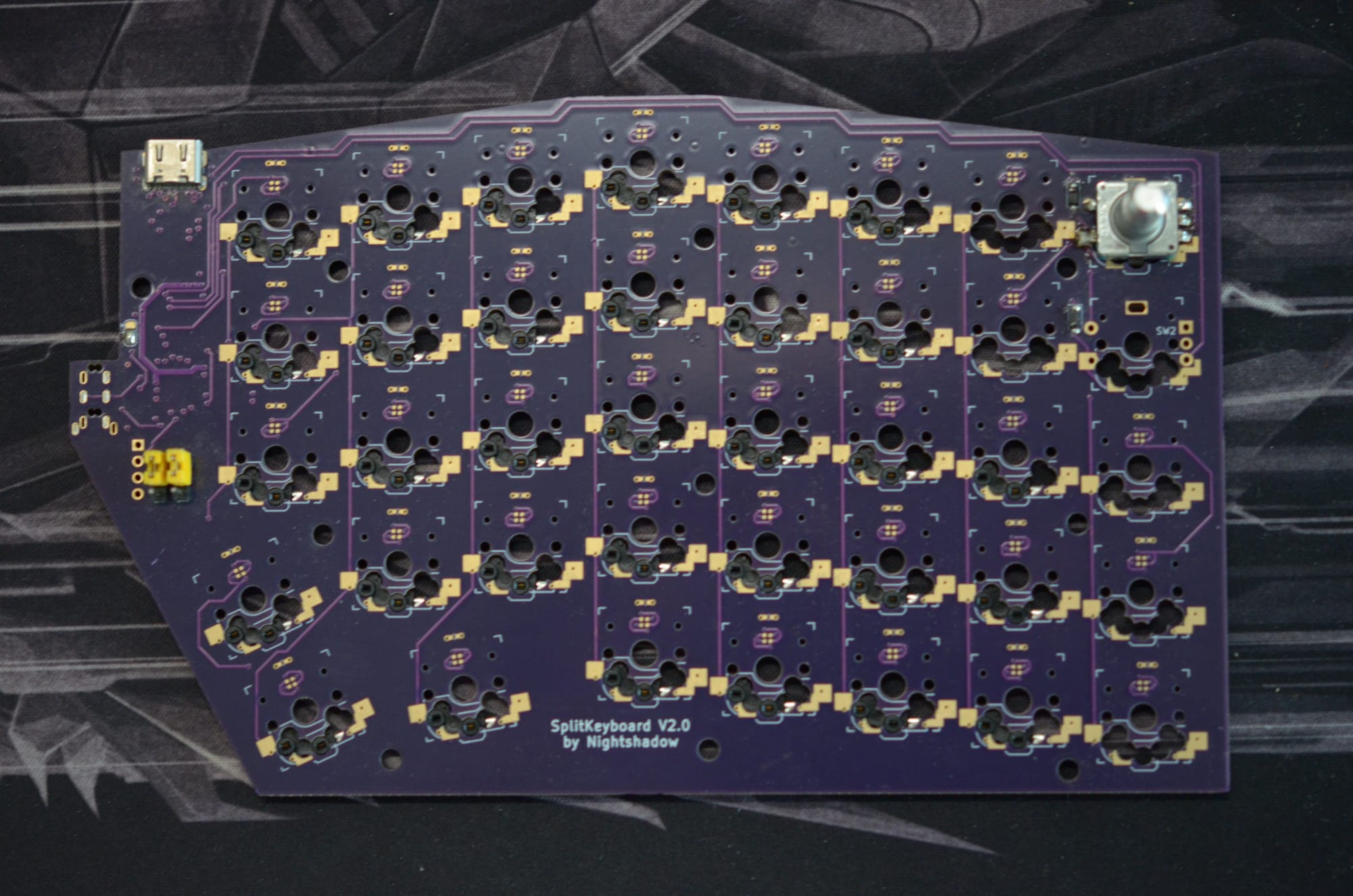
Version 2 aimed at refining the hardware. I changed the footprint of the keys to support either direct mounting or hot-swapping, while I kept the mirrored PCB design for reduced cost. I also modified the key switch placement and added one key column as can be seen in the pictures below
Issue
While the idea with supporting both directly soldering the key switches and hot-swappable capability sounds nice in theory in practice this did not really work out like I wanted it to. The keyboard layout still felt lacking to me, since I am used to a full sized keyboard with a num pad and additional function keys (I primarly use the Logitch G710+).
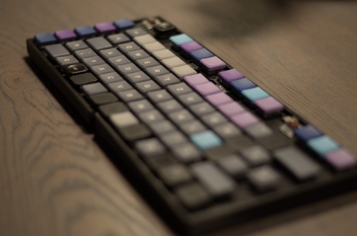
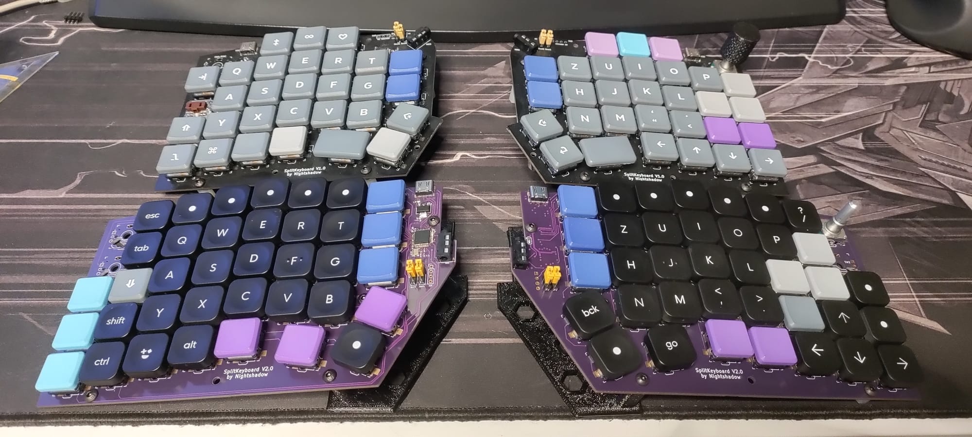
Version 3
This is where the project reached its current peak. I made several significant changes to the layout and functionality:
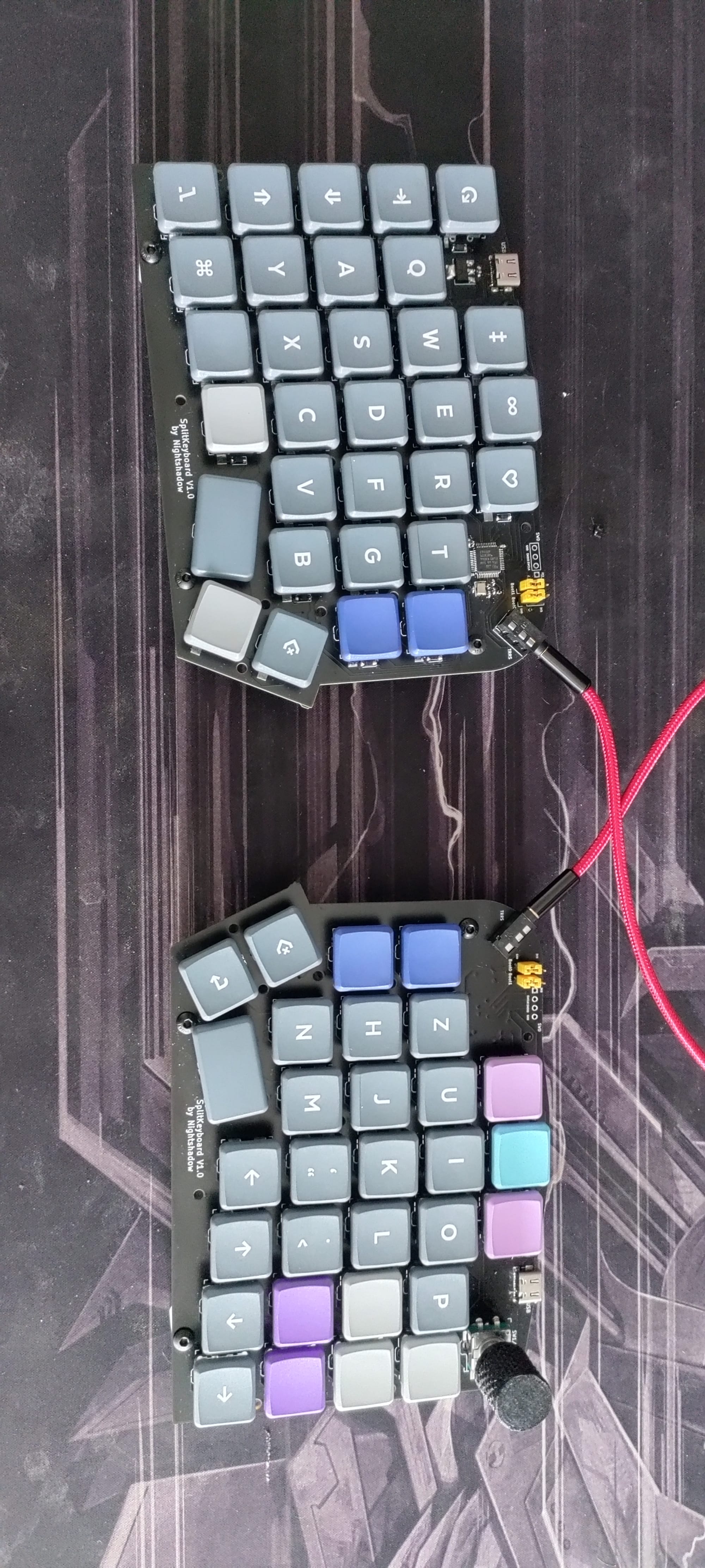
- Layout: Rearranged keys to mimic the familiar feel of the Logitech G710+.
- Numpad: Added a dedicated Numpad with its own USB C connection.
- Integration: Designed the PCB so the left and right halves can be combined, although tight tolerances made this a mechanical challenge.
The assembly process had its hurdles. I realized halfway through that I had soldered every single diode in the wrong orientation. After some tedious desoldering and rework, the hardware was ready.
Left Splitkeyboard
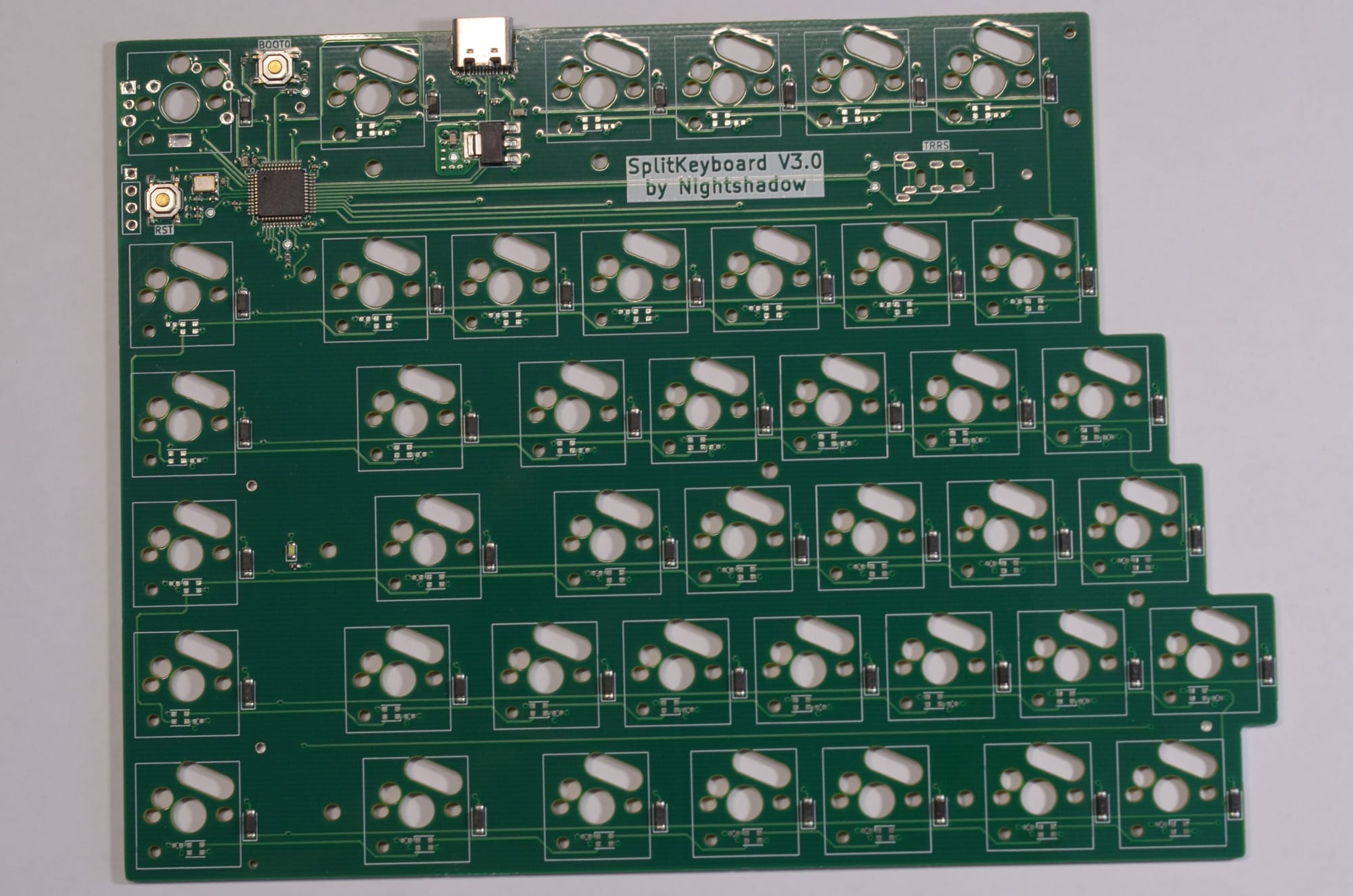
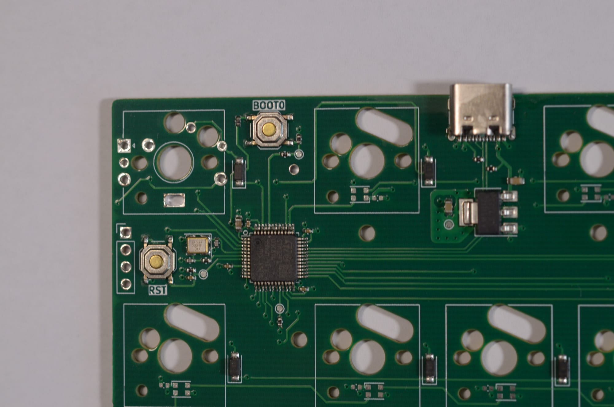
Left PCB of Splitkeyboard V3.0
Right Splitkeyboard
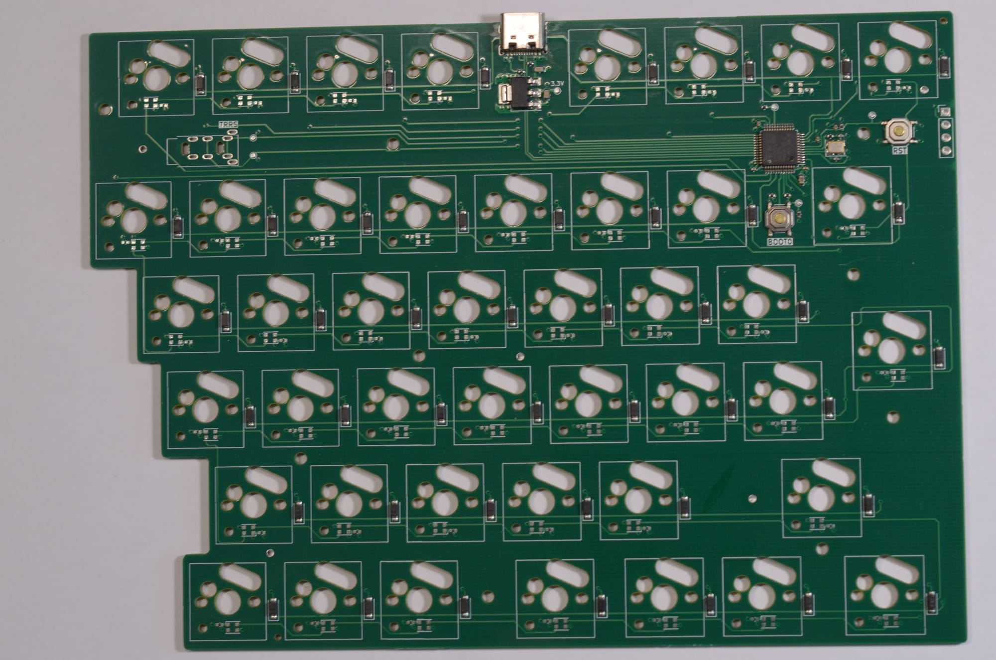
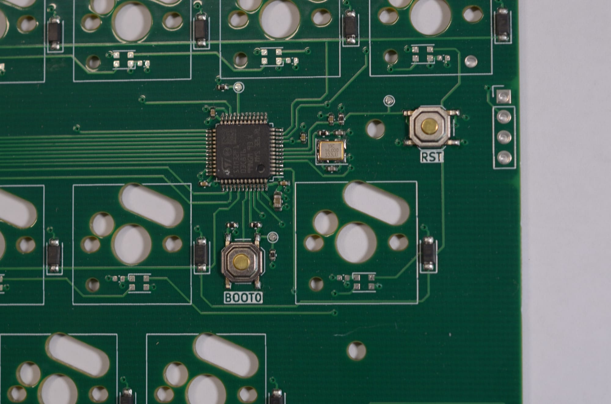
Right PCB of Splitkeyboard V3.0
Numpad
Numpad PCB of Splitkeyboard V3.0
I know that the silkscreen show V2.0, I am so sorry!
Firmware Implementation
With the hardware fixed, the focus shifted to QMK. I forked the original github repository and create my own custom QMK repository
Setting up the environment was straightforward:
python3 -m pip install --user qmk
qmk setup
Flashing the board required specific commands for the main halves:
qmk compile -kb splitkeyboard_v3 -km experimental
qmk flash -kb splitkeyboard_v3 -km experimental
and for the numpad:
qmk compile -kb splitkeyboard_v3_numpad -km experimentalLayout Splitkeyboard
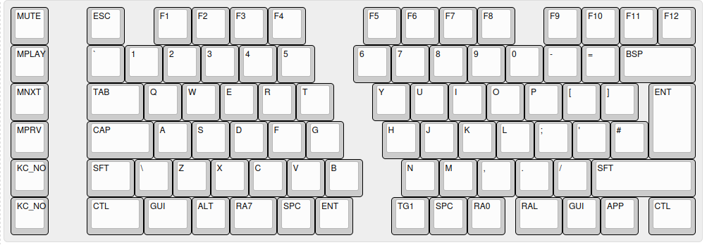
For the more specific of the configuration I strongly suggest reading the QMK documentation.
Images

Outlook
The keyboard is now fully functional and showing up as a DFU device. However, the journey does not end here. For future versions, I am considering:
- ZMK Firmware: Transitioning to ZMK to explore wireless capabilities via Bluetooth. This would require changing the MCU from an STM32F103 to an NRF device, that is tuned for wireless communication and low power operation to run on battery
- Housing: Designing a 3D printed or CNC machined case to protect the PCBs. This should give the keyboard a more premium feel and add some weight.
- Refining Tolerances: Improving the PCB edge connectors for better physical joining of the halves. Especially the connection for the normal keyboard configuration needs some improvement. Currently the cable do not allow that configuration.
Building a keyboard from the ground up was fun and challenging, but the result is a unique tool for my daily workflow. I would say that I learned a lot and had a fun time as well, even with the occasional struggles that come with such a project. Lets see if I get the time to create a newer version in the future.
Sources
Hardware Designs can be found here: https://github.com/Nightshadow1258/SplitKeyboard (later version use different branches, I am not sure if this is the best way to preserve them, but for now it is what it is :D) This
Is create a fork of the original QMK firmware, that can be found here: https://github.com/Nightshadow1258/qmk_firmware